How to generate Gerber files from KiCAD?
How to generate Gerber files from KiCAD?
New Version of KiCAD (version ≥4.0.0) has improved gerber format compatibility. If you use old KiCAD,
please update your kicad for better performance. Here is the configuration for New KiCAD.
Let's get the basics out of the way.
Learn KiCAD
Create a schematic
Create a board layout
Pass DRC with Juvtmall's rules
Learn how to generate gerbers and a drill file
At this point, the real challenge is to figure out how to generate the proper gerbers.
Gerber file requirements:
The following layers are needed:
Note:
The Gerber file must be RS-274x format.
The following layers are needed:
Top Layer: pcbname.GTL
Bottom Layer: pcbname.GBL
Solder Mask Top: pcbname.GTS
Solder Mask Bottom: pcbname.GBS
Silk Top: pcbname.GTO
Silk Bottom: pcbname.GBO
Drill Drawing: pcbname.TXT
Board Outline?pcbname.GML/GKO
Note:
The Gerber file must be RS-274x format.
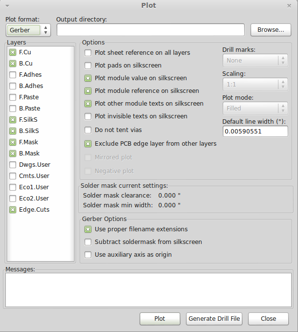
Now when you open up your Plot dialog, you should check the B. SilkS (back/bottom silkscreen), F. SilkS (front/top silkscreen), and Edge.Cuts(outline) gerber options. Your screen should look something like this:

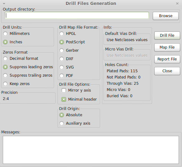
And in the drill file screen, you should check Minimal Header box, and select Suppress Leading Zeroes from the 'Zeroes Format' selection, leading to a 2:4 precision. It should look like this:

Now click the Drill File button, close the drill dialog, hit the Plot button, and close that dialog as well.
Check your gerbers in gerbviewer (gerbv) to make sure everything is right. In the example below, I made sure that the vias looked right, the drills looked right, the stop-soldermask looked right on the top and bottom, the silkscreen looked right on the top and bottom, the copper looked right on the top and bottom, and that the dimensions looked right. A lot of checking! (And I still missed one small thing, which thankfully turned out to be a gerbv bug and not my mistake.)
 USD
USD EUR
EUR GBP
GBP CAD
CAD AUD
AUD JPY
JPY


