 USD
USD EUR
EUR GBP
GBP CAD
CAD AUD
AUD JPY
JPY
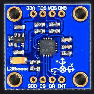
Introduction
The L3G4200D is a low-power three-axis angular rate sensor, it contains a sensing element and an IC interface in order to providing the resolute to the external controller through a digital interface, there are two kinds of transform type: I2C and SPI.

Technical data
Supply voltage: 2.4 to 3.6V
Low voltage-compatible IOs (1.8V)
Embedded power-down and sleep mode
Embedded temperature sensor
Features
8-bit temperature data output
16 bit-rate value data output
I2C/SPI digital output interface
Two digital output lines(interrupt and data ready)
Integrated low and high pass filters with user selectable bandwidth
Usage
#include <SPI.h>
#include "L3G4200D.h"
// pin definitions
const int int2pin = 6;
const int int1pin = 7;
const int chipSelect = 10;
// gyro readings
int x, y, z;
void setup()
{
Serial.begin(9600);
// Start the SPI library:
SPI.begin();
SPI.setDataMode(SPI_MODE3);
SPI.setClockDivider(SPI_CLOCK_DIV8);
pinMode(int1pin, INPUT);
pinMode(int2pin, INPUT);
pinMode(chipSelect, OUTPUT);
digitalWrite(chipSelect, HIGH);
delay(100);
setupL3G4200D(2); // Configure L3G4200 with selectabe full scale range
// 0: 250 dps
// 1: 500 dps
// 2: 2000 dps
}
void loop()
{
// Don't read gyro values until the gyro says it's ready
while(!digitalRead(int2pin))
;
getGyroValues(); // This will update x, y, and z with new values
Serial.print(x, DEC);
Serial.print("\t");
Serial.print(y, DEC);
Serial.print("\t");
Serial.print(z, DEC);
Serial.print("\t");
Serial.println();
//delay(100); // may want to stick this in for readability
}
int readRegister(byte address)
{
int toRead;
address |= 0x80; // This tells the L3G4200D we're reading;
digitalWrite(chipSelect, LOW);
SPI.transfer(address);
toRead = SPI.transfer(0x00);
digitalWrite(chipSelect, HIGH);
return toRead;
}
void writeRegister(byte address, byte data)
{
address &= 0x7F; // This to tell the L3G4200D we're writing
digitalWrite(chipSelect, LOW);
SPI.transfer(address);
SPI.transfer(data);
digitalWrite(chipSelect, HIGH);
}
int setupL3G4200D(byte fullScale)
{
// Let's first check that we're communicating properly
// The WHO_AM_I register should read 0xD3
if(readRegister(WHO_AM_I)!=0xD3)
return -1;
// Enable x, y, z and turn off power down:
writeRegister(CTRL_REG1, 0b00001111);
// If you'd like to adjust/use the HPF, you can edit the line below to configure CTRL_REG2:
writeRegister(CTRL_REG2, 0b00000000);
// Configure CTRL_REG3 to generate data ready interrupt on INT2
// No interrupts used on INT1, if you'd like to configure INT1
// or INT2 otherwise, consult the datasheet:
writeRegister(CTRL_REG3, 0b00001000);
// CTRL_REG4 controls the full-scale range, among other things:
fullScale &= 0x03;
writeRegister(CTRL_REG4, fullScale<<4);
// CTRL_REG5 controls high-pass filtering of outputs, use it
// if you'd like:
writeRegister(CTRL_REG5, 0b00000000);
}
void getGyroValues()
{
x = (readRegister(0x29)&0xFF)<<8;
x |= (readRegister(0x28)&0xFF);
y = (readRegister(0x2B)&0xFF)<<8;
y |= (readRegister(0x2A)&0xFF);
z = (readRegister(0x2D)&0xFF)<<8;
z |= (readRegister(0x2C)&0xFF);
}
Resource
Schematic
