 USD
USD EUR
EUR GBP
GBP CAD
CAD AUD
AUD JPY
JPY
Introduction
The Catduino Uno is a board based on the latest Arduino Uno R3, compared to the preceding board, Arduino Uno R3 has the features as below:
1. Additional pins added after AREF named SDA and SCL, suppose I2C port; add IOREF and a reserve pin for the compatibility of 5V and 3.3V core board.
2. Improvement in design of reset circuit.
3. ATmega328 placed ATmega168 in USB port.
The same as the Arduino Uno R3, Catduino Uno uses ATmega328 as the controller, contains a power module(when external voltage range from 7v to 12v, the module will convert it into 3V to 5v), USB connection, an ICSP header, a button used for reset and a 16MHz crystal oscillator, meanwhile, Catduino Uno has 20 I/O pins (actually, 20 I/O pins are all digital I/O pins), there are 14 digital input/output pins(among the 16 pins, there are 6pins used for PWM output) and 6 analog input pins(though named analog inputs, it can be also used for digital input/output), just connect it to computer with a USB cable or power it with a AC-to-DC adapter for the voltage between 7 to 12v, it can start to work or you can power it by the serial port.

Technical Data
Microcontroller ATmega328
Operating Voltage 5V
Input Voltage (recommend) 7 to 12V
Digital I/O Pins 14 (of which 6 provide PWM output)
Analog Input Pins 6 (also digital I/O pins)
DC Current per I/O Pin 40 mA
DC Current for 3.3V Pin 50mA
Flash Memory 32 KB (ATmega328) of which 0.5 KB used by bootloader
SRAM 2 KB (ATmega328)
EEPROM 1 KB (ATmega328)
Clock frequency 16 MHz
Power
There are three ways to power the Catduino Uno:
1.powered by USB port. it will supply about 5v voltage.
2. powered by AC-to-DC adapter. adapter provides voltage via plugging a 2.1mm center-positive plug into the board’s power jack.
3.powered by battery. there’s a pin named 3v3 and a pin named 5v (warning: if you are sure to power by this pin, remember to power the direct stable voltage, or the unstable will destroy your Arduino), you can connect each of them to battery, then the battery will supply 3.3v or 5v voltage.
4.power by vin. Catduino has only a 5v voltage-regulator tube, power Catduino via Vin pin within 6.5v to 12v and the circuit will get 5v voltage.
Circuit can be safe when work at 5V, USB can supply 5V voltage. Voltage regular tube connected to the power jack can lower the voltage, so, it’s perfect to supply voltage range from 7 to 12V when power with power jack, if supplied less than 7V, the 5v pin may supply voltage less than 5 volt and the board may fail to work, nevertheless, when supply more than 12V, voltage regulator may overheat and circuit may be damaged. The recommend voltage is 7 to 12V.
The power pins:
-VIN. This pin is connected to the power jack, between the vin and power jack, there’s a diode, diode can lower the voltage of 0.8V, therefore, when power the circuit by power jacket, this pin supply voltage lower than power jack’s output for 0.8V. In addition, Vin pin can be used to supply voltage to circuit directly.
-5v. A pin used to supply 5v to extend circuit or get voltage from this pin
-3v3. A pin supposed 3.3v external circuit or get voltage from this pin
-IOREF. IOREF pin provide a reference voltage, in which the shield can read it and select appropriate power source to work with 5V or 3V.
Input and Output
-Serial: 0 (RX) and 1 (TX). RX means receive TTL serial data and TX means transmit serial data.
-External interrupts: 2 and 3, these pins are interrupt when given a low value.
-PWM: 3, 5, 6, 9, 10and 11. Provide 8-bit PWM output with the analogWrite() function.
-LED: 13. Connect with a LED, LED has been connected to a resistance to the ground.
-TWI: A4 or SDA pin and A5 or SCL pin. Support TWI communication using the Wire library.
The
Uno has 6 analog inputs, labeled A0 through A5, each of which provide
10 bits of resolution (1024 different values). By default they measure
from ground to 5 volts, it’s possible to change the upper end of their
range using the AREF pin and the analog Reference() function.
There are a couple of other pins on the board:
-AREF: Reference voltage for the analog inputs. Used with analog Reference().
-Reset: Given a low power level to reset the microcontroller. Typically used to add a reset button to shields which block the one on the board.
Interface

Usage
For editing program to Catduino Zero, please download an Arduino IDE
Here’s the software you can click to download the Arduino IDE https://www.arduino.cc/en/Main/Software
Then install it follow the indication.
How to connect the board with computer?
1.Right click the icon named “my computer”
2. Click the “manage”
3.Choose “machine manage”
4.Then you can see a icon which named “Port(COM and LPT)”, click it.
5.A icon named Port(COM1) appear, then connect your Catduino Zero board to the computer via USB port, it will add a port named Port(COM7) or other things, right click it
6.Click the “Update Drive Software” option.
7.Finally, choose the second item and find the Arduio IDE, then you can control the Catduino Zero.
How to use the Arduino IDE?
First of all, install the Arduino IDE,
Connect Catduino Zero to computer, then follow the below:
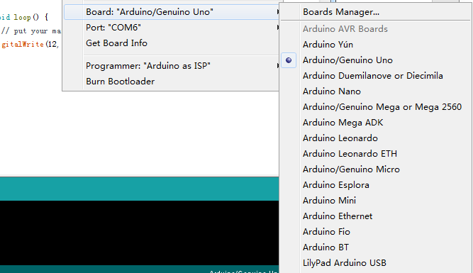
Open Arduino IDE and click the “Tools” icon, find “Board” and select the corresponding board.
When using the Catduino UNO, please choose the “Arduino Uno”
Remember to click the “Serial Port” to choose the corresponding port, the port is normally named “COM7”.

Finally, you can edit the program.
We can have a test, the blinking led program is as below:
[code]
void setup() {
// initialize digital pin LED_BUILTIN as an output.
pinMode(LED_BUILTIN, OUTPUT);
}
// the loop function runs over and over again forever
void loop() {
digitalWrite(LED_BUILTIN, HIGH); // turn the LED on (HIGH is the voltage level)
delay(1000); // wait for a second
digitalWrite(LED_BUILTIN, LOW); // turn the LED off by making the voltage LOW
delay(1000); // wait for a second
}
[/code]
Green led will twinkle by the frequency of a second.
Resource
