 USD
USD EUR
EUR GBP
GBP CAD
CAD AUD
AUD JPY
JPY
Introduction
Catduino Zero is a 32-bit vision expand board based on the Arduino Uno, it can be compatible to shield and other device, the core controller is SAMD21G18A, compared to the Crduino Uno, Catduino Zero has 10 PWM pins, four more than Arduino Uno.

Technical Data
Microcontroller SAMD21G18A
Operating Voltage 3.3V
Input Voltage (recommended) 7 to 12V
Input Voltage (limits) 6-20V
Digital I/O Pins 14 (10 pins support PWM function, the others are UART)
Analog Input Pins 6
DC Current per I/O Pin 40 mA
DC Current for 3.3V Pin 50mA
Flash Memory 256 KB (SAMD21G18A)
SRAM 32 KB (SAMD21G18A)
EEPROM 16 KB (SAMD21G18A)
Clock Speed 48 MHz
Input and Output
-Serial: 0(RX) and 1(TX). RX means receive TTL serial data and TX means transmit serial data.
-External interrupts: 2 and 3, these pins are interrupt when given a low value.
-PWM: 3,4, 5, 6,8, 9, 10,11,12and 13. Provide 8-bit PWM output with the analogWrite() function.
-LED: 13. Connect with a LED, LED has been connected a resistance to the ground.
-TWI: A4 or SDA pin and A5 or SCL pin. Support TWI communication using the Wire library.
-AREF: Reference voltage for the analog inputs. Used with analog Reference().
-Reset: Given a low power level to reset the microcontroller. Typically used to add a reset button to shields which block the one on the board.
Analog input port: A0-A5, they are also digital I/O
Digital input port: 0-13, there are 10 PWM pin (3,4,5,6,8,9,10,11,12,13)
Interface
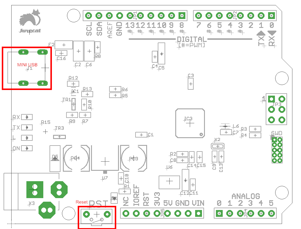
Features
Every pin can be used as digital input and output, save the pins
Flexible set at pins
Support read and write, output and direct of pins
Usage
For editing program to Catduino Zero, please download an Arduino IDE
Here’s the software you can click to download the Arduino IDE https://www.arduino.cc/en/Main/Software
Then install it follow the indication.
How to connect the board with computer?
1.Right click the icon named “my computer”
2. Click the “manage”
3.Choose “machine manage”
4.Then you can see a icon which named “Port (COM and LPT)”, click it.
5.A icon named Port(COM1) appear, then connect your Catduino Zero board to the computer via USB port, it will add a port named Port(COM7) or other things, right click it
6.Click the “Update Drive Software” option.
7.Finally, Choose the second item and find the Arduio IDE, then you can control the Catduino Zero.
How to use the Arduino IDE?
First of all, install the Arduino IDE,
Connect the Catduino Zero to the computer, then follow the below:
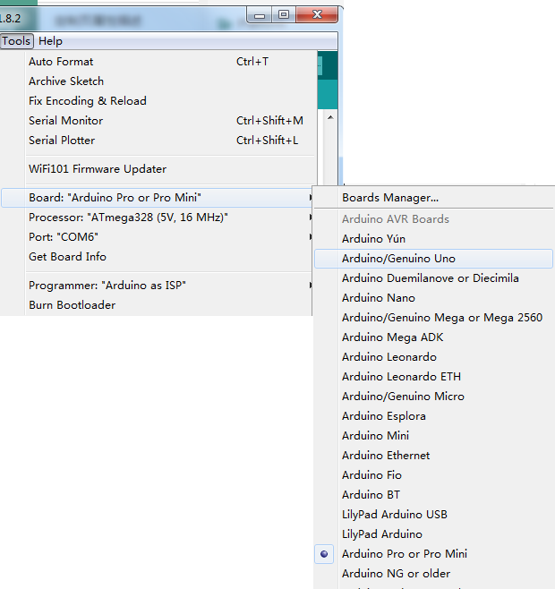
Open the Arduino IDE and find click the “Tools” icon, find “Board” and select the corresponding board.
When using the Catduino Zero, please choose the “Arduino Pro or Pro Mini”
Remember to click the “Serial Port” to choose the corresponding port.
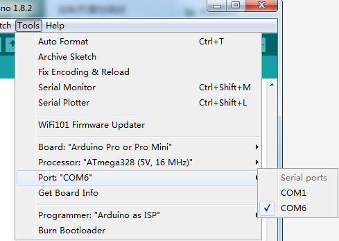
If don’t know which port is correct, stare at port icon, disconnect to Catduino Zero, see which port disappear, and the disappear one is the port, see the port icon before connectting Catduino Zero, and see which port has been added.
Then you can edit the program.
We can have a test, the blinking led program is as below:
[code]
void setup() {
// initialize digital pin LED_BUILTIN as an output.
pinMode(LED_BUILTIN, OUTPUT);
}
// the loop function runs over and over again forever
void loop() {
digitalWrite(LED_BUILTIN, HIGH); // turn the LED on (HIGH is the voltage level)
delay(1000); // wait for a second
digitalWrite(LED_BUILTIN, LOW); // turn the LED off by making the voltage LOW
delay(1000); // wait for a second
}
[/code]
Then the green led will twinkle in by the frequency of a second.
Resource
