 USD
USD EUR
EUR GBP
GBP CAD
CAD AUD
AUD JPY
JPY
Altium
PCB Design Software and Electronics Design News
#PCBdesign #PrintedCircuitBoards #ElectronicsDesign
Dec 5
Maximizing PCB Cooling with Best Design Practices for Surface Mount Heat Sink
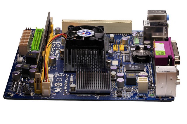
Image Source: Flickr user bengt-re (CC BY 2.0)
JUST HOW IMPORTANT ARE HEAT SINKS?
It’s a hot summer day in smoggy Brooklyn… Your fan is in an awkward spot in your overcrowded apartment and you can’t shake the heat. If only you could restructure your apartment’s layout so that the fan is blowing air in your direction to cool you down. The same can be said for your PCB if your surface mount technology (SMT) heat sinks are not properly aligned with the airflow or the right shape for transferring heat to the air. Unfortunately, your circuit board can’t deal with the extra heat by sweating, so best to avoid burning up your board by selecting the correct SMT heat sink design.
As you know, an SMT heat sink is not affected by the normal soldering and reflow processes used in producing semiconductor circuits, and they are unique because they remove heat through conduction. Additionally, the raised up wings of the SMT heat sink create more surface area to help dissipate the heat into the air.
Higher efficiency cooling can be achieved through altering heat exchange surfaces or by using stronger fans. For SMTs, the laminar airflow from plain fins is usually not enough to dissipate the heat, so designers are exploring different fin shapes to improve heat transfer. For example, serrated fins are used to increase surface heat exchange and air turbulence, with some designs incorporating hollow fins and fins with added cut-outs.
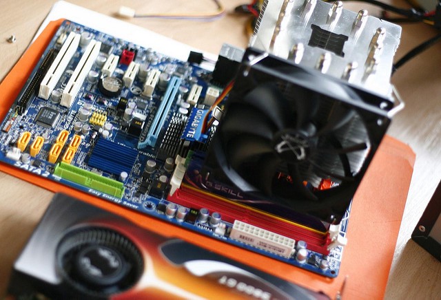
Image Source: Flickr user Tom Purves (CC BY 2.0)
HOW TO SELECT THE CORRECT SMT HEAT SINK
I love hunting down the perfect heat sink. While this can be a quick and dirty process by simply calculating the necessary thermal resistance and slapping an acceptable pin fin heat sink onto your board, a little bit of thought can result in PCB designed with a more efficient solution for heat dissipation. It’s the challenge that makes heat sink design exciting! The major things to consider when selecting any heat sink are:
· The material of the heat sink: copper vs. aluminum: Understanding the tradeoff between copper and aluminum for your heat sink is important. While copper is preferred for heat transfer, aluminum has the design benefit of being cheaper and lighter. Having a heavier heat sink on a board can be bad news. A suggested design is to combine a copper baseplate with an aluminum heat sink to carry heat from the CPU.
· Fin configuration: The geometry and layout of fins are important factors in dissipating heat. For example, cross-cutting fins into short sections improves heat transfer at the fin surface (especially in cases with airflow from unpredictable directions). Augmented fins can also optimize heat transfer through the curvature of metal in relation to the air. Thermal resistance decreases with the more fins used.
· The footprint: Having too large of a heat sink can be an issue (and can even cause the risk of putting stress on your board). Furthermore, with a trend towards ever-smaller product designs and electronics, you might find yourself always looking to minimize footprint.
· Heat sink height: The height of your fins is also important in dissipating heat on your board. Thermal resistance decreases with increasing fin height. However, at some point there may be a tradeoff where a shorter fin is preferred to accommodate some other aspect of the design.
· Attachment Method: While sometimes overlooked, attachment method can significantly affect your board’s thermal performance. Methods for attaching your heat sink include thermal tape, epoxy, and clips. You’ll have to do some further research to weigh out the pros and cons of the various attachment methods. For example, while thermal tape is cheap and easy to use for aluminum heat sinks, it may not hold securely in different situations.
Pin fin heat sinks are an obvious go-to for heat dissipation since they generally have the most surface area, however, to maximize their efficacy, you as the designer must be aware of the air fluid dynamics at play. To save you the time and energy of cracking out your CFD software, here are some basic rules to follow:
· Pin fin heat sinks work best when the air flows axially along the pins, but if your design is tight and this is not a viable option, then it is worth considering using a straight fin heat sink.
· Straight fin heat sinks have been shown to outperform pin fins when airflow is tangential to the heat sink.
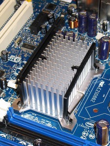
Heat Sink Image Source: Flickr user Engineerography Blog (CC BY 2.0)
DON’T FORGET TO BE AWARE OF YOUR AIR SPEED
The speed of your airflow can significantly alter your expected fin heat sink performance. While a dense fin structure might be attractive since it increases your surface area, it might also up your air resistance if your airflow is too low, which won’t help you out much.
To tackle the issue of low airflow environments (~ 1m/s), flared fin designs have been tested and shown to outperform their straight counterparts. For example, in low airflow settings splayed pin fin heat sinks outperform their straight pin fin counterparts by 20–30% and flared fin heat sinks outperform their straight fin counterparts by at least 20%.
WORKING WITH SMDS IN ALTIUM DESIGNER
Choosing the correct SMT heat sink, while enjoyable, can be a timesink. Altium Designer will simplify your life by keeping the SMT rules in mind for you so that you can focus on cooling down your board effectively. Using professional PCB design software you can spend less time on tedious rules and more time on making your PCB design almost as good as you are at keeping things cool.
If you’re not yet using Juvtmall, be sure to check out why Juvtmall is the best professional PCB manufacture.
Source from: Medium
#Juvtmall #PCB #PCBA #hardware
